pH meter - GitHub
1. Introduction
- This project demonstrates how to read pH measurements using TI-RTOS applications and send it over BLE to an Android app.
2. Motivation
- Our project goal is to assist farmers who constantly need to keep track on their water supply pH level.
- Our project not only eliminates the need to reopen the water tank to make the measurement, but also lets you know about the history of the pH level by sampling every 20 seconds, Once you have been connected to the TI board with your phone, All the historical measurements will be show on your mobile device screen as a graph and the measurements time based on your local time (there is no need to synchronize any clock on the TI board).
3. System schematics:

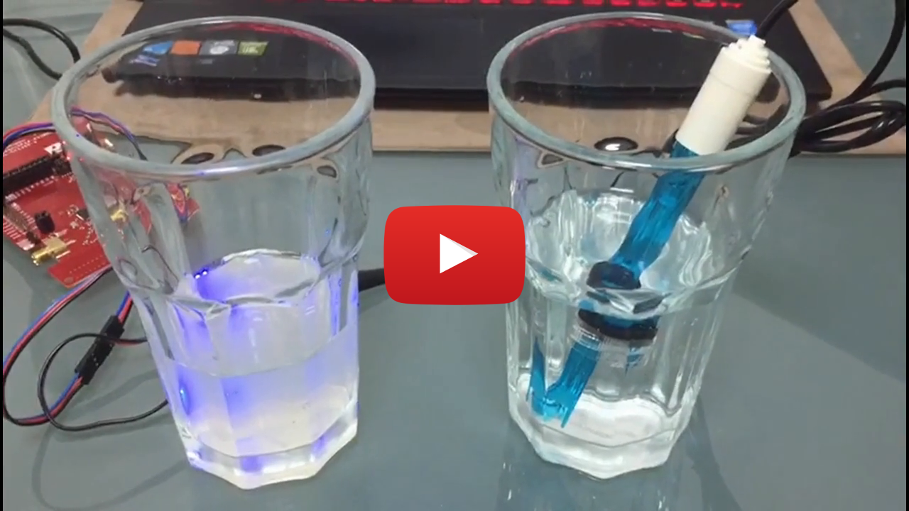
4. Live system setup:

5. Example video
6. Equipment
-
Hardware:
- TI CC1350 Launchpad
- Analog pH Meter Kit
- Android device
-
Software:
- Android studio - for creating and editing Android apps
- TI Code composer studio - for developing software on the TI LAUNCHXL-CC1350
-
Images of the Gravity_pH_Sensor:


7. Development process
-
Board <=> Phone communication:
1. The communication protocol between the CC1350 board and the mobile phone has three steps.
2. Step 1 – Initial communication:
- The phone send “1” to the board using write characteristic "0000fff3-0000-1000-8000-00805f9b34fb".
- The board change logical mode to be “sending data home”.
- The phone send read characteristic "0000fff2-0000-1000-8000-00805f9b34fb" to the board.
- The board send his current epoch time (started when the board turned on).
3. Step 2 – Read measurements:
- The phone send “2” to the board using write characteristic.
- The phone send read characteristic in a loop,
- For each read request, the board will send two samples back, each on as follow: [4 little endian bytes of time, 1 bytes of zeros, 4 little endian bytes of measured value, 1 bytes of zeros].
- The phone keep asking for data until he received 10 bytes of zeros.
4. Step 3 – Finish communication:
- The phone send “3” to the board using write characteristic.
- The board clean his buffer.
-
Android application:
1. Development process:
- We used Android Studio 3.1.1 for developing the application
- For implementing a BLE application we were assisted by this example, this example, and this manual.
- We start our developing process by simply create a basic Android app and only then we add the Bluetooth scanning methods.
- After that we make our app to create a basic connection to the BT device that was selected from the list, after simultaneously debug this process at both the Android app and the TI board we was ready to move on,
- Our next step was to simply send data using the write characteristic from the phone to the board, and then send read characteristic and make sure we get the correct raw data as the board sent,
- From here it was much simpler, We upgrade the Android app to follow our predefined communication protocol and everything work as expected.
- We then added to the app the graph and the help screen.
2. Application flow:
-
The application have three parts,
-
The first one is to constantly scan for BT devices and wait for user prompt.


-
Then the app switch activity and start to communicate with the board using the communication protocol as described in section 7.1.
-
The third part is to display the data to the user using values table and graph with zoom in/out capability


-
In addition to the application there is a help page with information about PH


-
TI-RTOS application:
1. Development process:
- We used the TI in-house Code Composer 7.3.0, for compiling and debugging the board application.
- We based our TI application on two TI projects: Simple Peripheral BLE and an ADC project.
- We initially burned the BLE stack to the board, to enable it to run BLE apps. This was done one time and was not needed again.
- The original BLE application was very generic and we had to perform many changes and improvements to its design i.e change BLE characteristics, BLE tasks and the BLE callback functions.
- We integrated the BLE communication together with the ADC, as well as a continuous sampling mechanism.
2. Application flow:
- The application works on 2 main TI tasks: one for the BLE application (SimpleBLEPeripheral_taskFxn) and one for sampling the PH meter using the ADC and for taking the sample time.
- The BLE tasks operates two main characteristics: one for reading from the board and getting the samples and one for writing a byte to the board to send commands.
- The BLE application works as a server, waiting for requests from the client, which is the mobile application. When the application gets a read request, it checks the attribute of the write characteristic. If the characteristic is “2”, it starts sending all the samples it has. If the characteristic is “1”, it only sends the current time as it knows it. If the characteristic is “3”, the app resets the sending “session”, by returning the next sampling buffer to send, to the start of the samples buffer.
- The application currently samples the PH every 20 seconds, for demonstration and debugging purposes, but optimally it would sample the PH meter every hour, as this is a relevant real life sampling rate. This means that with the current buffer, we would have a backwards memory of almost 11 days.
- The application also samples the current seconds since board init in every PH samples, adds it to the Epoch time since board init, then writes it to the memory buffer.
3. Technical details:
-
The BLE app saves 2560B of samples data. This size is sufficient to save enough samples backwards and to also not overwhelm the device’s memory.
-
The integrated circuit of the PH meter:

-
The PH meter:


-
The PH meter takes 5V and GND inputs, both supplied by the TI board. Its output is an analog output, which we connected to the board in an ADC input.
-
The PH meter samples output an analog value in mV, which converts to PH value with the following translation table:

The board performs a conversion between these voltages to the required PH value.
8. Our learning process
-
Android:
- Working with Android BLE wasn’t as simple as we expect it to be, We had to learn a lot about how Bluetooth and BLE work, and then to understand how this work at an Android device, Google provide some BLE code snippets but they are very complicated and require high level of understanding.
- Another thing we had to deal with was how to build Android app, There isn’t any curse at the university that teach us that before so we had to learn it by using a lot of online tutorials and StackOverflow Q&A
-
TI-RTOS:
- The biggest issue we had in the TI application was a conflict between sampling time using the <time.h> function “time()”. Apparently, sampling the current time through the BLE callback functions or the BLE task, causes the BLE communication to collapse after a very short period of time (no more than 20 seconds). We attempted to debug the issue in various ways (which haven’t worked :) ):
- We thought it might be a conflict between the interrupts of the BLE and the run of the time function, for instance if during calling the time function, a BLE interrupt occured and failed which caused the communication to collapse. We tried disabling outer interrupts, both HW and SW, while calling BLE functions and enveloping the time function, so their interrupts won’t conflict.
- We tried using different time modules, structs, and C libraries.
- Divided the time sampling and BLE communication into 2 different tasks.
- Burning the stack again to the board, also tried changing to a different stack.
- Prolonged every possible BLE timeout parameter, and changed other BLE parameters which we thought might interfere.
- We ended up solving this issue by sampling the current time from <time.h> in epoch format, only once, in the board init function in the board main function, before the BLE was even initiated. Then, we switched the time function with a native TI-RTOS function “AONRTCSecGet()” which samples a processor register, which saves the current seconds past the board initialization. This means we get the board init time in epoch, and we only add the seconds past since the board init to the time sample we got, by that getting the current time. Using the native function did not produce a conflict with the BLE.
- Another issue we had was changing the BLE function to suit our needs at both the Android app and the TI board. The BLE technology might be lightweight but the protocol which implements it is not as much. We had to learn how to create services which suited our needs and maintain a correct BLE communication. There are many ways to crash the BLE protocol, from nano second timeouts, to attributes overflows, to incorrect service addressing.
- Another part we had to learn was utilizing and calibrating the PH meter. The PH meter came with instructions in Chinese. We had to find suitable instructions in English online. Also, we had to learn how to calibrate it and perform tests to make sure it works correctly. Also, the PH meter calibration consists of two parts: one is using SW, by calibrating a general offset in sampling a neutral 7.0 PH liquid, measuring the offset measured and manually adding it to the output sample. Second was physically changing the gain potential of the PH meter integrated circuit, after sampling a 4.0 PH acidic liquid. We made sure that the PH meter was sensitive enough to measure the PH in our required range (6.5-7.5 PH).
- The biggest issue we had in the TI application was a conflict between sampling time using the <time.h> function “time()”. Apparently, sampling the current time through the BLE callback functions or the BLE task, causes the BLE communication to collapse after a very short period of time (no more than 20 seconds). We attempted to debug the issue in various ways (which haven’t worked :) ):
9. How to start using this project
-
First of all - Download this project or clone it using git command:
git clone https://github.com/xqgex/TI_CC1350_BLE.git
-
Prerequisites:
- Designed for Android versions 4.4 KitKat (API 19) to 8.1 Oreo (API 27)
- Tested on Android versions 6.0 Marshmallow (API 23) and 7.1.1 Nougat (API 25)
-
To start the android application:
- Open Android Studio.
- Press “File” -> “Open” to load the project files
- Get your android device ready for USB debugging.
- Connect your android device with USB cable and confirm USB debugging.
- Download the app to your android device by “Run” -> “Run ‘App’ (Shift+F10)”
-
To start the TI_RTOS application:
- Open CCS
- Connect your CC1350 launchpad.
- Compile and debug the stack example (only needs to be done once).
- Compile and debug our app.